Blade Motion and Control
Contents
Blade Motion and Control
“Engineers sometimes take movies of the blade motion with a camera mounted on the hub. The results are spectacular enough that no one wants to show them to the pilots.”
—Ray W Prouty (Helicopter Aerodynamics I)
As the helicopter moves from a hover flight state to a forward flight state, the rotor wake undergoes quite a bit of transformation. This special forward flight region 0< \({\mu}\) <0.15 is generally referred to as the transition region where proximity of the rotor tip vortices to the following blades leads to impulsive loadings, which in turn results in high noise and vibrations. Needless to say transition region is not comfortable for people inside the helicopter or for those in the neighbourhoods it flies over. The momentum theory-based inflow together with BET is not enough to model all the aerodynamic effects occuring at certain blade sections due to BVI phenomena and vortex theory-based models are needed to model them. However, momentum theory results detailed in the last chapter represent the rotor inflow reasonably well from the point of view of power consumption as it captures the dominant flow effects necessary for getting the power expenditure right.
Since helicopter blades are essentially highly flexible cantilevered beams that get subjected to very high loads, it seems natural to ask if we are losing out on complete physical understanding of the aerodynamics by not talking about the blade elastic deformations. For e.g. consider a rotor in steady hover such that the airfoil sections that make up the blade get subjected to steady aerodynamic lift, drag and moment. From our discussions until now it is clear that the way the pilot would command a change in thrust (in order to be able to hover with different payloads, or climb up and down) is via a pitch change of the all the blades together referred to as the collective control. It is also clear that the commanded pitch of the blades would be less than the angle of attack that the blade sections experience due to the inflow through the rotor disk. While the focus of the current course is rotor aerodynamics, it cannot be talked about in isolation without discussing the structural aspects of rotor operation. With that in mind, this lecture is a brief overview of the operational aspects of a rotor.
How does one achieve \(V_F\)>0?
This is not a trivial question to ask. From basic understanding of airfoil aerodynamics, it is relatively obvious that to achieve hover at a given MTOW, the rotor collective needs to be increased until the helicopter leaves the ground. Once in hover, the main rotor thrust vector needs to be tilted so that a forward component accelerates the helicopter until enough parasite drag builds up to counter it and steady state forward flight is established. One possible mechanism of achieving forward motion would be to move the helicopter CG ahead of the rotor shaft. The thrust vector would induce a pitch down moment on the entire aircraft which would lead to the thrust vector tilting and accelerating the rotorcaft forward. Helicopters achieve this using a simpler mechanism, relatively speaking, that doesn’t involve anything as complicated or cumbersome as moving the CG of the aircraft.
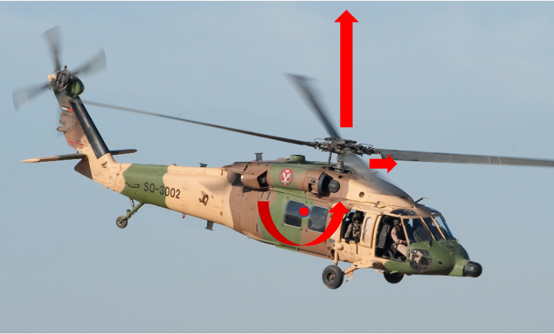
Forces and moments balance about CG (modified from [source])
![[source]](https://en.wikipedia.org/wiki/Sikorsky_UH-60_Black_Hawk#/media/File:Jordanian_Air_Force_UH-60_Black_Hawk_helicopter_(cropped).jpg)
Net force and moment about the CG of the aircraft should equal zero
Vertical component of thrust = aircraft weight
Horizontal component of thrust = aircraft drag
Net roll moment about CG = 0
Net pitch moment about CG = 0
Control
Understanding the machinations of axial (hover/climb) flight is relatively straightforward. The same intuition acquired when learning about fixed-wing propellers carries over to VTOLs in axial flight. This changes dramatically, however, once there is flow in the plane of the rotor disk or edgewise flight.
Swashplate
The rotor collective was already discussed in the context of controlling thrust generation to achieve hover/climb. In general, rotorcraft control is achieved by generating forces, moments, or a combination of the two, at the rotor hub (the structure at the center of the rotor disk that keeps everything together). While varying thrust production is required for horizontal/vertical acceleration, moments are required for the aircraft to pitch and roll. Much like a fixed-wing aircraft, rotorcraft can use control surfaces on the empennage to facilitate pitch motions in forward flight. However, in hover and low speed flight, the main rotor becomes the sole entity that is capable of providing these moments.
You can watch this capability of the rotor in action below. The V-280 valor is an experimental tilt-rotor design but in the case of low speed maneuverability, the same principles are at work as in the case of a conventional helicopter. In particular, aircraft pitch changes are achieved by introducing hub moments at the centers of each rotor (roll on the other hand, for this particular configuration, is achieved via differential thrust). How are these moments achieved?
from IPython.display import YouTubeVideo
YouTubeVideo('xRiZhCAmr6Y', width=800, height=400)
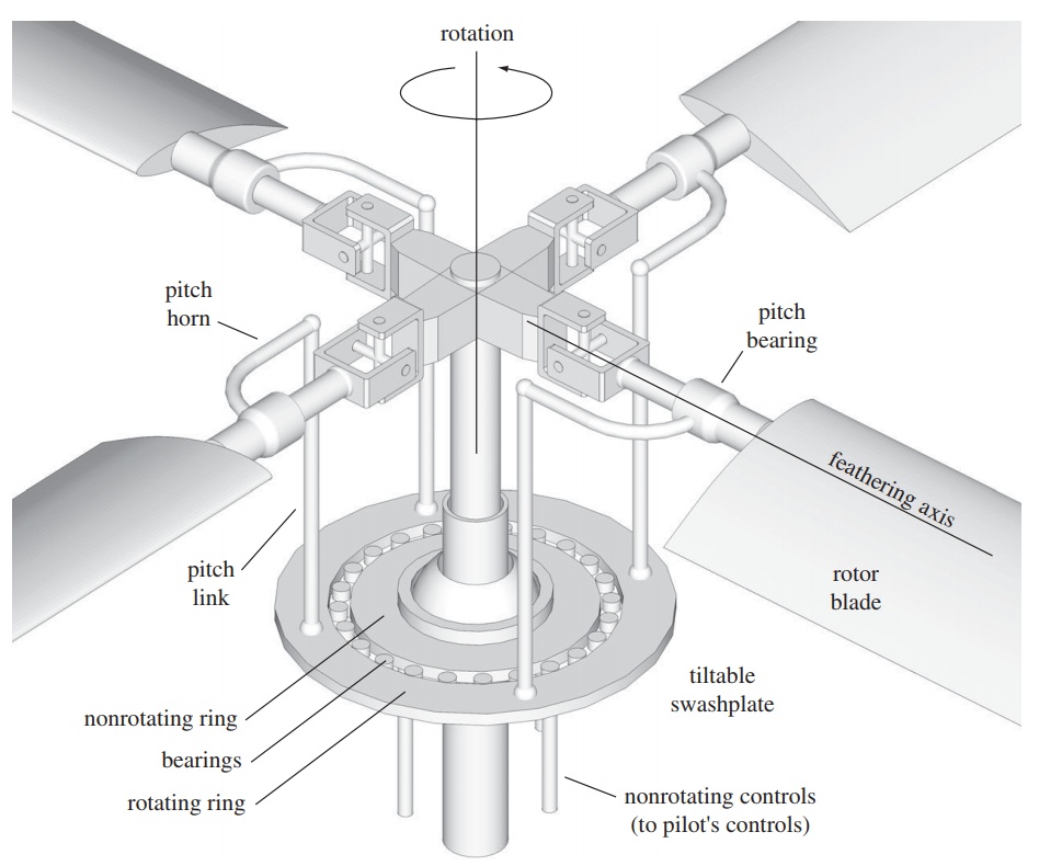
The primary mechanism involved in instigating blade motion, such that desirable rotor forces and moments are obtained, is called a swashplate. The way it achieves this is via a harmonic change in the blade pitch angle and is capable of providing the following scheduling to the pitch angle of a rotor blade.
Blade pitching
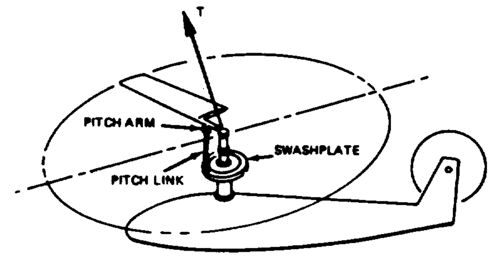
Helicopter rotor control [source]
$\(\theta = \theta_0 + \theta_{1c}\cos(\psi) + \theta_{1s}\sin(\psi)\)$
Wait, what!? Collective movement of the blade pitch is understandable, but one harmonic pitching cycle as the blade completes one revolution!? Doesn’t the rotor rotate at like 5-7 Hz!? Also, why is the the pitching of harmonic type and not any other function?
One way of achieving forward tilt of the thrust vector, for example, would be by tilting the entire rotor hub assembly itself. This is the case for some autogyros. Powered rotors usually achieve this using the swashplate mechanism and the pilot control of the swashplate tilt is achieved using a central control stick. The control linkages are arranged such that a forward stick motion, for example, generates a forward thrust vector tilt of the rotor. Collective pitch control is achieved using a side stick. The controls layout in case of multi-rotor designs can get complicated - for e.g. longitudinal control (forward stick) in case of tandem helicopters is achieved by forward tilt of both rotor disks as well as an change in the thrust share between the two rotors. All this while making sure that the overall torque is balanced.
Note
Controlling the rotor blade pitch at even higher frequencies (\(\approx\) 40 Hz) is possible and has been demonstrated in experimental test flights. This falls under the realm of active rotor control, specifically individual blade control or IBC.
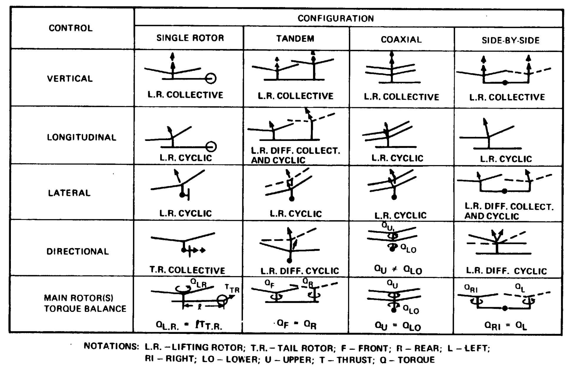
Helicopter control achieved in different configurations [source]
from IPython.display import YouTubeVideo
YouTubeVideo('UyduIDPVVlE', width=800, height=400, start=140, end=219)
from IPython.display import YouTubeVideo
YouTubeVideo('-kWhNi-MZAM', width=800, height=400)
from IPython.display import YouTubeVideo
YouTubeVideo('HK-pNadi8eI', width=800, height=400)
In case of a fully rigid rotor 1, a swashplate tilt would produce a moment on the rotor hub in the direction of the tilt. This is due to the change in blade pitch angles as they undergo one revolution - increase in pitch angle where the swashplate is tilted up and a decrease where it is tilted down. In case of a pull of the longitudinal stick control (towards the pilot), the aircraft would pitch up due to an increase in the blade pitch (i.e. a negative \(\theta_{1c}\)) when the blades are close to \(\psi=180°\). Based on the harmonic variation of blade pitch angle over the azimuth, this automatically leads to an opposite effect 180° later i.e. at \(\psi=360°\).
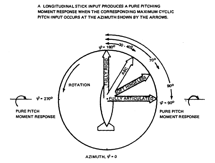
Azimuth of blade cyclic input to illicit pitch down response of aircraft [source]
The figure above carries additional details for some of the different kinds of rotor systems on helicopters. The following discussion will attempt to throw light on the significance of the other arrows shown here. They suggest that if one had an articulated rotor, for e.g. like the one on the UH60 design, then the pilot would need to increase blade pitch when the blade is at \(\psi=90°\) in order to generate rotor forces such that the helicopter experiences a net pitch-up moment. Of course the pilot does not have the direct capability to control the azimuth where the blade pitch can be increased. The pilot only moves the control stick in the cockpit around and the control mixer system then appropriately maps that movement to the pitch input to the blade based on whether the rotor system is articulated, hingeless or rigid rotor design.
Introduction of flapping hinge
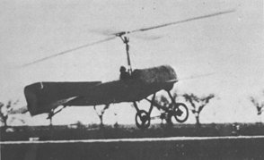
Autogyros (or Gyrocopters) are a class of aircraft with a pusher prop and a rotor that is tilted backwards and rotates freely in the air.
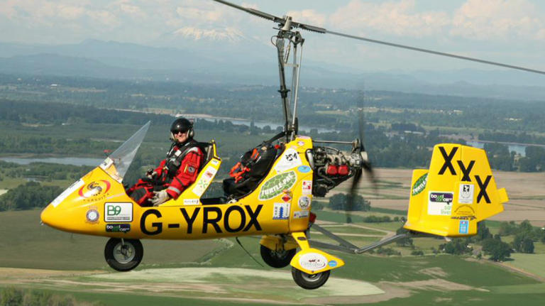
Autogyro [source]
![[source]](https://en.wikipedia.org/wiki/Autogyro#/media/File:362934-gryocopter-pilot-norman-surplus-uploaded-august-11-2015-taken-from-surplus-website.jpg)
Concieved before helicopters became mainstream
Take-off only possible with some run-up
Alternately, engine power diverted temporarily to rotor
Rotate with low pitch setting and then quickly raise it
Aside
Why does the autogyro pictured here not have a tail rotor?
Early autogyro designs had blades that were rigidly connected to the rotating shaft. This led to a lateral lift assymetry, due to different dynamic pressures, when the rotor spun in forward flight.
noticed on autogyros by Cierva
fixed by putting up (pin joints) mechanical hinges at the blade roots
allowed each blade to flap up and down independent of other blades
Highest blade lift occurs at \(\psi=90\deg\), ergo blade flaps up at \(\psi=180\deg\)
opposite effect on retreating side
Blade flapping leads to in-plane coriolis forces
lead-lag hinges needed to relieve in-plane fatigue loads
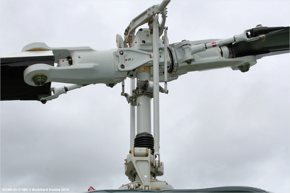
The freedom of movement in the flap direction can lead to corioilis forces on the blade as it undergoes flapping motion during rotation. In other words, having a flap hinge can lead to motion of the blade in the plane of the rotor disk. This is refered to as the lead-lag motion. As counter intuitive as it may sound, this motion is a natural result of coriolis forces on the blade CG and can lead to high lead-lag or chordwise blade stresses if nothing is done to accomodate for it. Consequently, rotor blades also tend to have an additional hinge close to the rotor center of rotation in order to allow in-plane blade motion.
Schematic of the rotor hinges and swashplate [source]
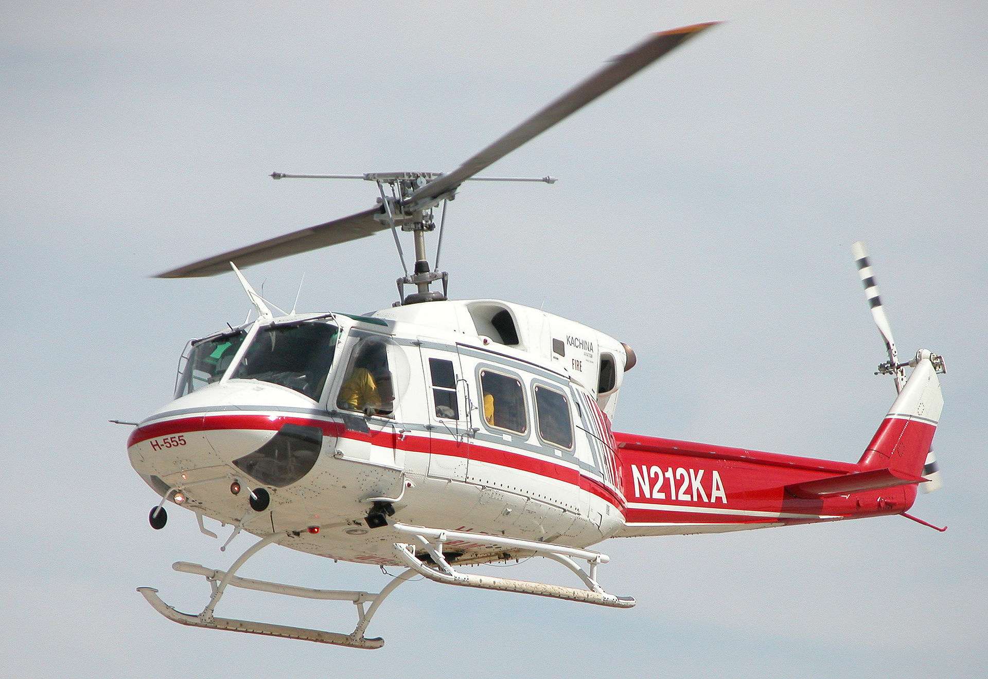
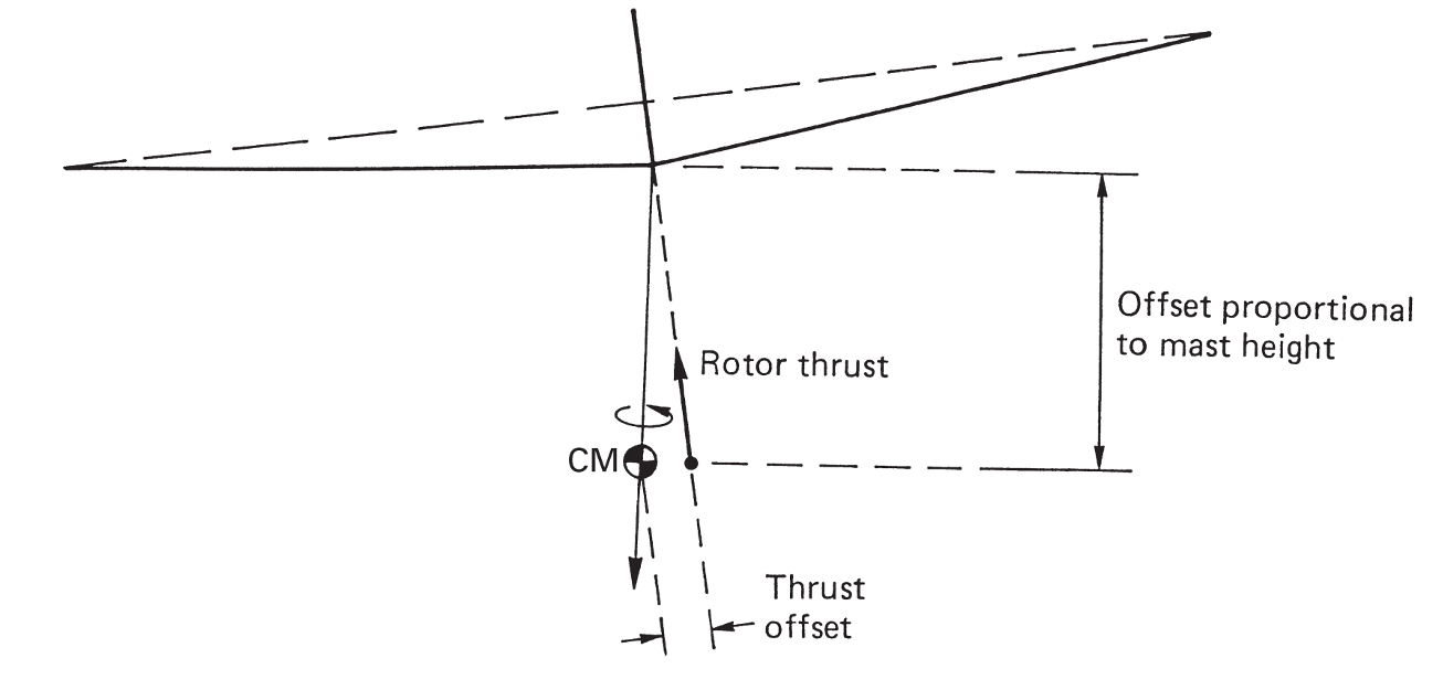
This simple design solution has persisted to this day and is implemented (in some form) on all current rotor designs with more than 2 blades. As is evident from the figure above, the hinges are not necessarily at the center of rotation but can have an offset. A flap hinge offset facilitates a moment to be generated at the rotor hub, due to the tension in the blades, whenever the tip path plane is not perpendicular to the shaft. This is why designs that have this feature (for e.g. UH-60) are more agile than designs that don’t (for e.g. UH-1 has a teetering-type rotor where the hinge is located at the center of rotation).
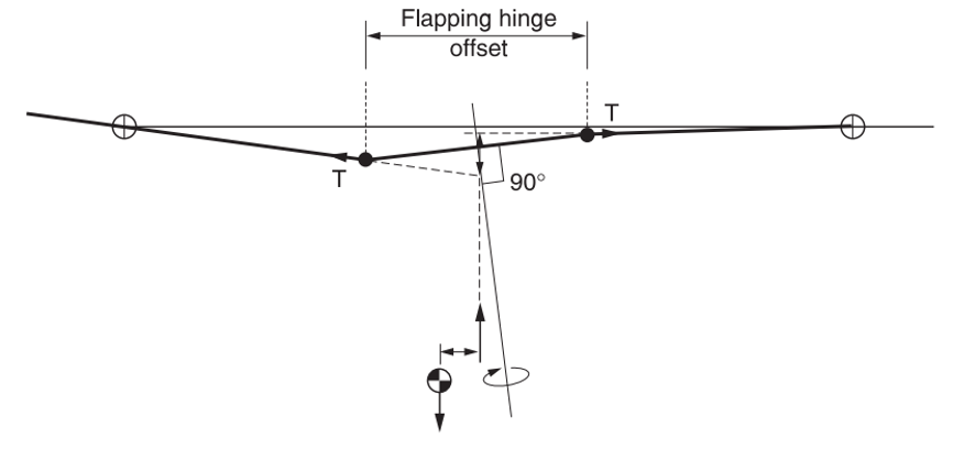
Moment couple due to flapping blades with hinge offset source
Blade flapping
Blade flapping refers to the out-of-plane motion of the rotor blades, as they undergo one rotor revolution, afforded by the flapping hinge or blade elastic flexibility. Flapping of the rotor disc generates moment at the rotor hub that in turn changes the orientation of the entire aircraft. Flap hinge is necessary to reduce the structural stresses experienced at the blade root and to remove the high roll moments that can arise if the blades were rigidly connected to the hub. If the flap hinge is located at the center of rotation itself, no bending moment from the blade can be transfered to the helicopter. This was true of the early autogyro designs and of teetering rotors.
Aside
While the autogyros had fixed-wings attached that could generate sufficient control in order to orient the aircraft and undergo maneuvers with requisite agility, the lack of moment transfer due to blade flapping seems like a pretty restrictive feature. In reality, teetering rotors (rotors where the flapping hinge is indeed exactly at the center of rotation) can generate moments about the helicopter CG by tilting the thrust vector. The resulting agility is not as good as that of articulated or hingeless rotor.
In steady flight, the blade motions undergo periodic motions and the flapping experienced by one blade can be given by the following expression -
Note that to have steady rotorcraft flight, the blade motion/aerodynamics have to be periodic. When the rotorcraft is undergoing maneuvers, the blade motion/aerodynamics are non-periodic for the transient period. Flapping of the blade, due to hinges or blade elasticity or both, leads to the blades motion be a function of the azimuth angle \(\psi\) only. This leads to the rotor disc taking up specific orientations in space based on the magnitudes of \(a_0\), \(a_1\), \(b_1\), etc. as shown below 2.
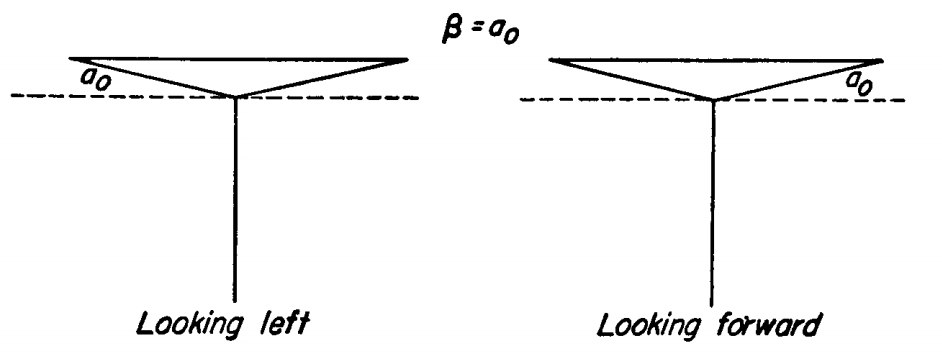
Rotor with β = a0
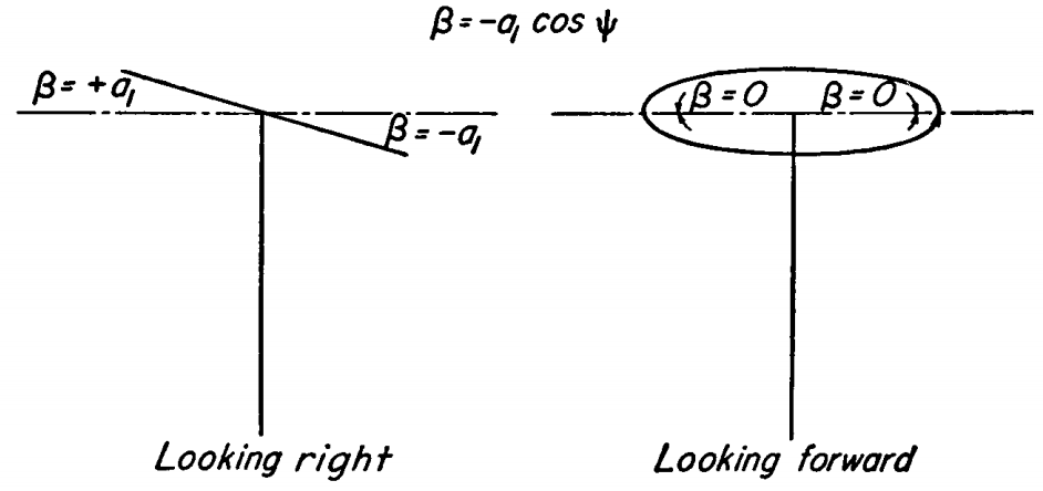
Rotor with β = -a1 cos ψ
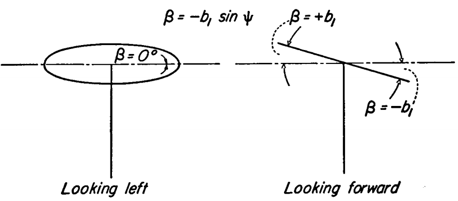
Rotor with β = -b1 sin ψ
\(a_0\) refers to rotor coning that occurs due to blade positions that balances the moments, due to the centrifugal forces and the lifting forces, about the blade hinge. Given the large magnitude of centrifugal forces on the rotating blades compared to the lifting forces generated by the blade, as was already discussed in a previous lecture, the coning angle is not large.
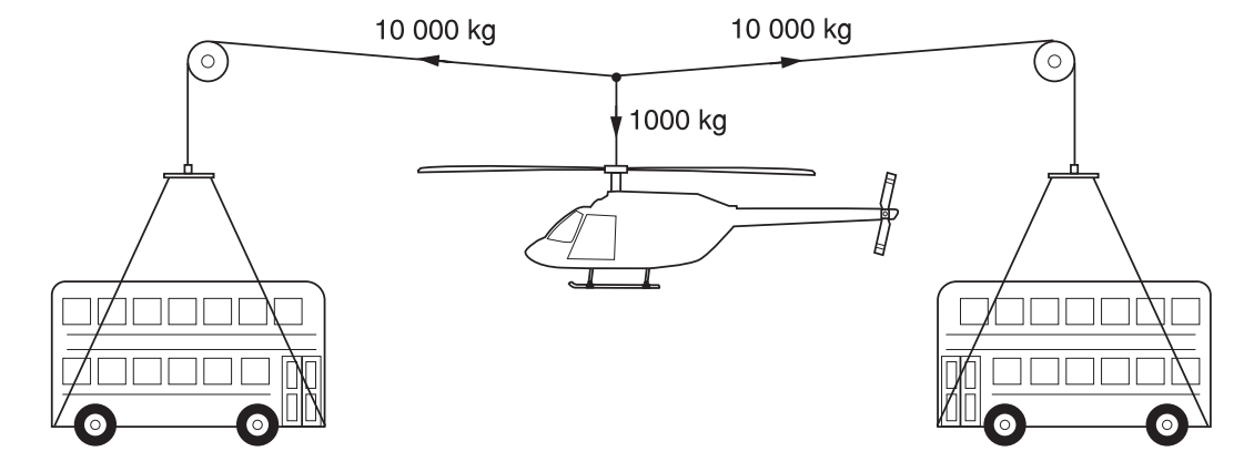
Schematic demonstrating the order of magnitude difference between the rotor centrifugal and thrust forces [source]
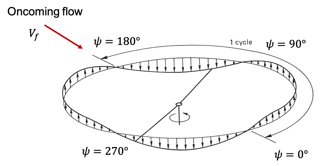
In forward flight, rotor coning leads to different effects of the oncoming flow velocity on the blade aerodynamics depending on the longitudinal position of the blade. When the blade is at \(\psi=180°\), the free-stream oncoming flow velocity \(V_f\) is such that it increases the overall blade section angle of attack. This results in higher aerodynamic loads and a corresponding increase in lateral blade flapping 90° later at \(\psi=270°\). The free-stream velocity has the opposite effect at \(\psi=360°\) (or 0°) so that now the blade flaps down 90° later at \(\psi=90°\). The overall effect is a rightwards tilt of the rotor disk. The preceding discussion is with regards to CCW rotors, in case of CW rotors the same physics applies but the rotor tilt would be in the opposite direction. It is easy to see that in the absence of rotor coning the free-stream will have similar effect on the fore and aft positions and such lateral tilting of the rotor disk would not occur.
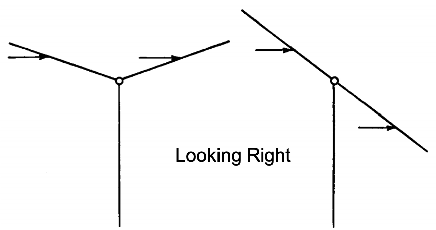
Side view of the effect of rotor coning on the local flow at the blade sections
Similarly, the lateral assemtry in dynamic pressure results in high aerodynamic loads at \(\psi=90°\) to which the blade responds with maximum flapping occuring at \(\psi=180°\). The opposite happens at \(\psi=270°\), low aerodynamic loads due to low dynamic pressure and a corresponding flap down motion at \(\psi=360°\). The overall effect is the rotor disk tilting back (\(a_1\)). High harmonic flapping can be seen as a warping of the tip-path-plane. This occurs as a consequence of additional harmonic effects on aerodynamic loading due to blade pitching, effects of the reverse flow region, elasticity in the blades etc.
Tip-path-plane of rotor undergoing purely 2/rev lateral flapping ($b_2$) [adapted from source]
Overall blade motion
The resulting blade motion due to blade pitching is of great aerodynamic relevance since blade section pitch is related to the section angle of attack. Likewise, blade flapping is related to the net out-of-plane velocity at a given blade section which, together with the section pitch angle, decides the angle of attack.
from IPython.display import YouTubeVideo
YouTubeVideo('Pu48f7s5Ru8', width=800, height=400)
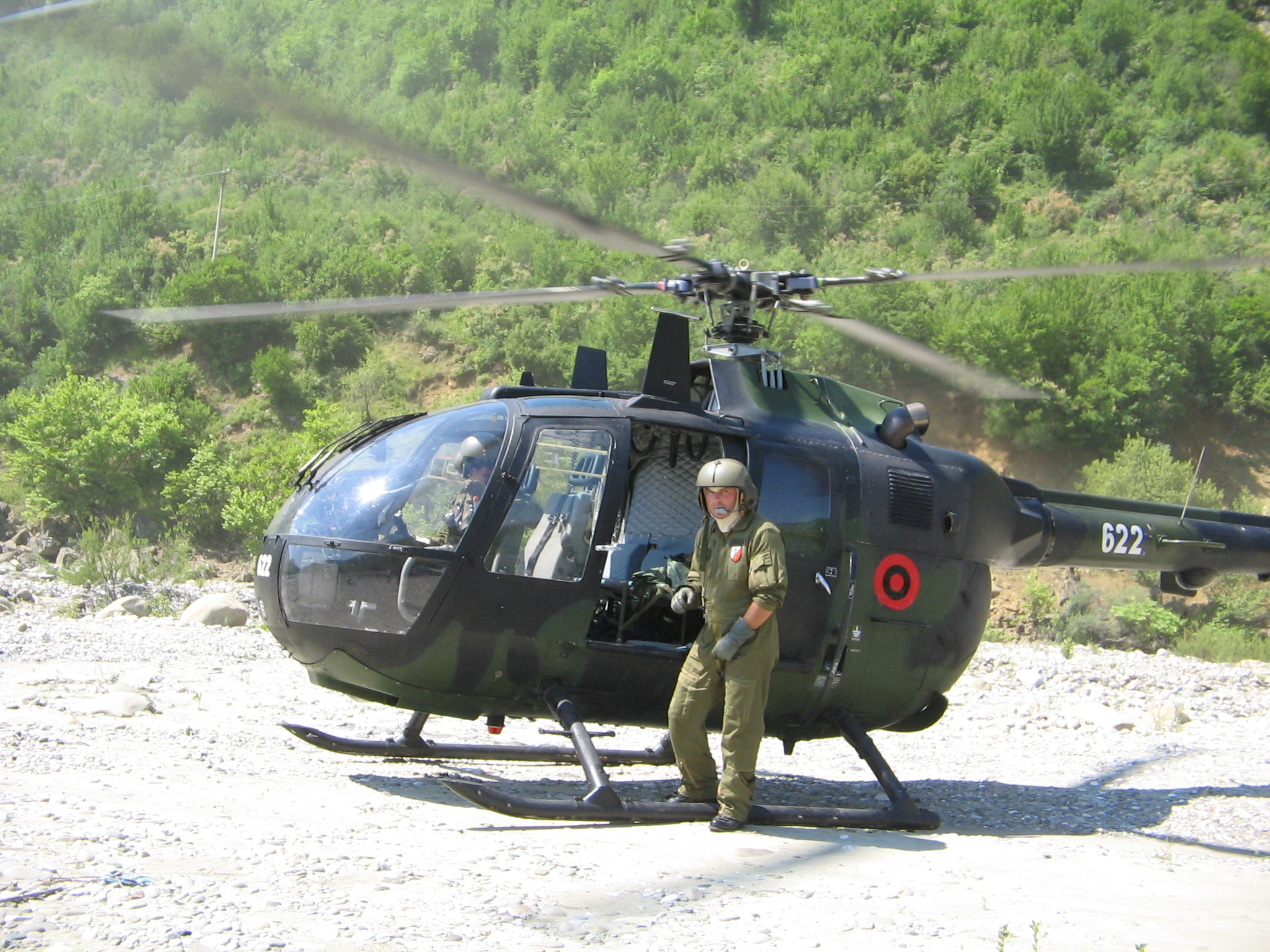
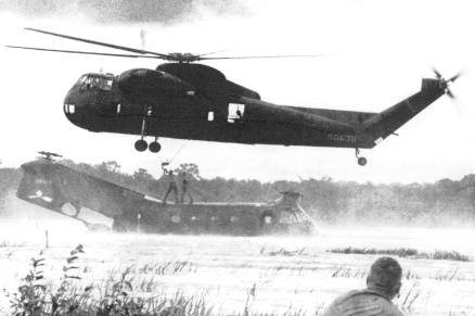
The video is of a Bo 105 helicopter that has a rotation rate of 7 Hz. So the clip has been slowed down considerably and only represents about 3 s worth of real-time action. Similarly, the video below shows even more dramatic blade deformation in flight. This can be partially attributed to the blade span on the S-56 helicopter which is more than double that of the Bo 105.
from IPython.display import YouTubeVideo
YouTubeVideo('srjbnvTWRJI', width=800, height=400)
The following shows the periodic elastic blade motion for a simulated Bo 105 rotor at \(\mu=0.3\). Given the slender nature of rotor blades cantileverd at one end, significant flapping can occur at the blade tips due to elastic bending as well. This is in addition to the flapping occuring due to the presence of a flapping hinge. Since these are also the locations where the highest dynamic pressure is encountered, it becomes imperative to accurately obtain the angle of attack of the blade sections there. Both, the rotor wake aerodynamics as well as the blade kinematics need to be solved accurately for that. The rotor aerodynamic wake solution gives us the inflow velocity and the blade deformation gives the structural flapping velocity. The two add up to give the net relative flow velocity together with the forward flight velocity.
from IPython.display import Video
Video("../../assets/ElasticBlade_4.mp4",width=400,html_attributes="loop autoplay")
Rotor vs propellers in edgewise flight
Forward (edgewise) motion of the rotor as a whole creates assymetry of dynamic pressure. If nothing is done, this simply results in more aerodynamic lift in the region of higher dynamic pressure. As revolutionary as it might have been to mechanically implement this during the early days of the evolution of the helicopter rotor system, pitching the rotor blade and thereby controlling the angle of attack has become the most reliable mechanism to overcoming the lateral assymetry of dynamic pressure via pitch change of the blades. Blade flapping due to elasticity of the blade or the presence of a flapping hinge also helps attentuate these effects.
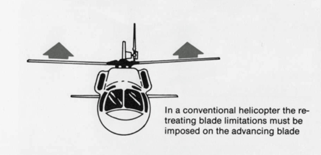
Rigid rotor requirement of roll moment balance [source]
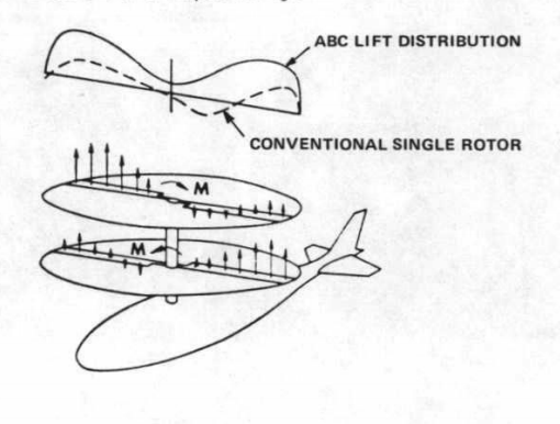
Having said that, a rotor design that is basically a propeller (i.e. no swashplate for blade pitching, no flapping hinges and rigid blades) placed horizontally on top of the helicopter fuselage presents a lot of interesting possibilities. Of course, the aforementioned problems wouldn’t magically go away. So the challenge is to come up with a solution strategy different from what the early pioneers of rotorcraft came up with. The rigid rotors based coaxial system, also refered to as ABC (advancing blade concept) rotor, jointly proposed by Boeing and Sikorsky is one such setup that is undergoing extensive tests currently to push the envelop of VTOL flight.
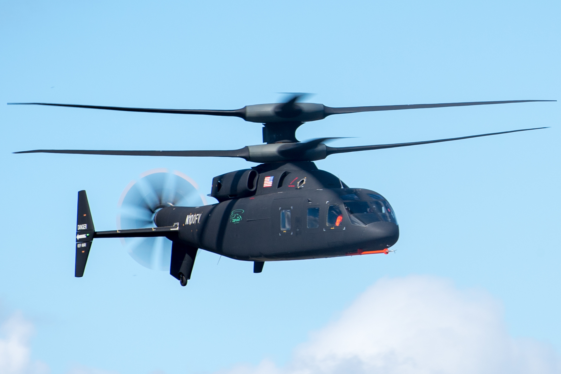
Sikorsky-Boeing SB-1 Defiant [source]
![[source]](https://en.wikipedia.org/wiki/Sikorsky%E2%80%93Boeing_SB-1_Defiant#/media/File:Sikorsky%E2%80%93Boeing_SB-1_Defiant_(cropped).jpg)
Schematic of thrust generated by coaxial rotor in forward flight [source]