Momentum Theory
Contents
Momentum Theory
“Fortunately, engineers and technologists do not wait until everything is completely understood before building and trying new devices…”
In case you were wondering that helicopters have been around for almost a century, surely engineers know everything there is to know about them. What contribution could you make to the state-of-the art in this field. The above quote is particularly relevant.
Objective
First order of business is to develop a framework to quantify a relation between the power necessary to develop a unit amount of thrust. One can imagine that this would be a highly relevant excercise in the early days of the invention of a rotorcraft - is rotor-based VTOL flight even allowed within the laws of physics?! The simplest framework that can be used to model the action of a rotor, which is also the framework that was used/developed by early practitioners in this field, and quantify the power consumption is called momentum theory. The idea is to model the dominant flow physics, which in the case of a rotor is a push to the flow opposite to the direction of the generated thrust, and evaluate its effect. As the course progresses, more and more from the rich feature-set exhibited by rotorcraft aerodynamics will be introduced along with ways to account for/model them.
The objective is to detail rotor analysis model called momentum theory and derive a relation between the following quantities
rotor radius R
thrust T generated
power P required
induced velocity \(v\)
Why is a new model even necessary?
Alternately, why can we not just solve the Navier-Stokes equations (NSE)?
An aerodynamicist in the early 20th century was very much familiar with the fundamental conservation laws governing fluid dynamics - the Navier-Stokes equations (NSE), a set of nonlinear partial differential field equations in space and time that should, in principle, give you the flow behavior for rotors (in hover, or forward flight state) much as they would for wings in forward flight. However, analytical solutions to the NSE are available only for a handful of very simple flows (or rather simple boundary conditions). Instead of waiting around for a powerful enough computational device to be invented to solve the most complicated form of the problem, aerodynamicists at the time solved the problem by introducing assumptions/idealisations to the rotor flow problem. The result is the momentum theory whose equations are much easier to solve.
Momentum theory-based equation are
simple and intuitive
solved using a hand calculator
match true results pretty closely
Turns out the dominant flow characterisitcs of a rotor are indeed dictated by these simpler equations. If one is seeking the relationship between T and P for a rotor of given R, momentum theory is a very simple alternative. Momentum theory provides us a simple framework of the flow phenomenology of lifting rotors. The flow problem is idealized so that it still models the dominant flow physics but simplified enough so that the number of problem variables are minimized. Notwithstanding how computationally intensive it is solve the full NSE for a rotor flowfield, staring at the end result or the equations that led to it is not going to be very helpful in understanding relationships between, for e.g., thrust and power.
Note
Lower level models such as momentum theory are great for all the reasons mentioned above. But with great model simplicity comes great responsibility (on part of the user) to always keep in mind the limitations/assumptions used, and whether they even apply for the problem at hand. One major pitfall of having a simple model is you will always get an answer. Whether it is appropriate or outright wrong depends on the application context. More on the application context below.
Fundamentals of momentum theory
How would you go about quantifying the amount of work done in order to accelerate said mass of air and keeping the helicopter aloft? Thats where the momentum theory comes in. Sure, there are issues of whether the aircraft can be controlled, structural stresses are not exceeded etc. but if there isn’t sufficient power to even operate, everything else is pointless. To evaluate required power, we adopt this model which was in fact used first for analysing ship propellers (ships were around way before aircraft were!).
For this, the rotor is modelled following the Rankine & Froude actuator disk model. As per this physical model, the propeller or rotor plane is assumed as a disk of zero thickness that supports a pressure difference/discontinuity but not in velocity. More on this below.
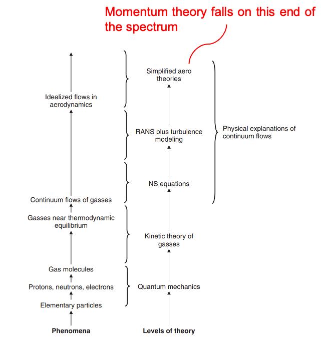
Heirarchy of physical theories [taken from "Understanding Aerodynamics" by Doug McLean]
ideal representation of the rotor
no losses
mass, momentum and energy conservation
…but so do the NSE!
based on Bernoulli’s fluid model
results in closed-form expressions
not possible with NSE
simplest rotor analysis theory!!
and quickest
dominant rotor flow physics modelled
some effects left out
tip vortices, viscosity, \(v\neq f(r,\psi)\)
Model details
Hovering rotor flowfield model in momentum theory
models only thrust, no torque
rotor as an actuator disk
pressure jump across rotor disk assumed uniform
velocity uniform and continuous across the rotor disk
continuity of (incompressible) fluid
rotor details
only radius accounted for
number of blade, chord, airfoil etc. ignored
control volume analysis for average flow velocity
flow is axisymmetric, incompressible, steady, inviscid
Mathematical formulation: Hover
The details of momentum theory are discussed here as they apply in the context of a helicopter rotor. In hover, the rotor generates thrust by propelling the surrounding fluid in the opposite direction. This requires energy, since the kinetic energy imparted to the surrounding fluid has to come from somewhere, and chemical energy of the fuel burnt onboard the helicopter provides this. In addition to the energy needed to ‘push’ the air (to hover), energy gets expended separately to overcome friction encountered by the rotor blades as well as imparting swirl to the flow (this takes additional kinetic energy). The latter is just a by-product of the rotational motion of the helicopter rotor. There are different variations to momentum theory, we’ll just be concerned with the simplest version. So, we ignore the viscous and swirl losses and consider the rotor operates by just pushing the air down.
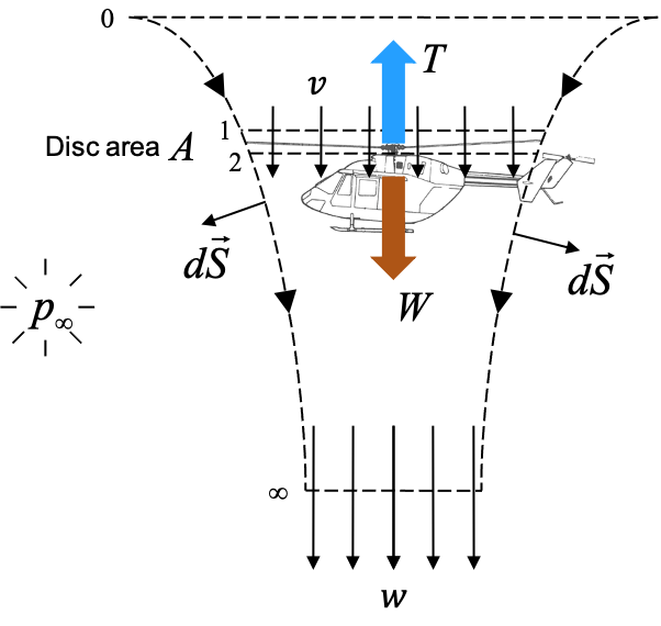
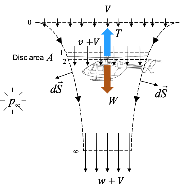
A control volume as shown in the figure below is considered and relation between T, P, R and v is obtained via the application of mass, momentum and energy conservation laws. The derivation below is for a rotor in hover i.e.
This includes vertical as well as horizontal velocities!
Hovering rotor flowfield model in momentum theory
The power estimate obtained above has been obtained without assuming any viscosity in the flow. So the power consumption cannot be attributed to any viscous losses and indeed is just one of the components of total power consumed in a real rotor. This power component is referred to as induced power. The quantity \(v\) is referred to as induced velocity, i.e. flow velocity at the rotor disk. This quantity is not just a coincidental by product of the formulation of equations shown above but a very fundamental physical entity to quantity accurately if one has any hope of obtaining not just power consumption, but also aerodynamic load distribution of the rotor disk. Of course momentum theory, in its simplest form presented above, deals with the entire rotor
The following observations can be made from the results obtained-
flow attains half the speed from rest at station 0 to the rotor disk at station 1
the other half is attained travelling from station 2 to \(\infty\)
a larger rotor disk is more efficient
operation at higher altitudes requires more power
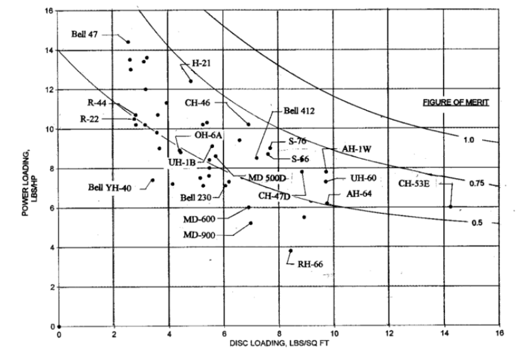
Here \(\frac{T}{P}\) is called power loading PL and DL refers to disk loading. Naturally, a high power loading is desirable and one of the measures of how efficient a rotor is. Disk loading is a fundamental attribute of a rotor and in-general is to be kept low - from the expression above it is obvious that this leads to high power loading. In reality, having a extremely large rotor (in order to keep DL low) is not always a viable option.
Applying the Bernoulli’s principle, a relation between velocity at a point in the slipstream and the corresponding pressure can be obtained.
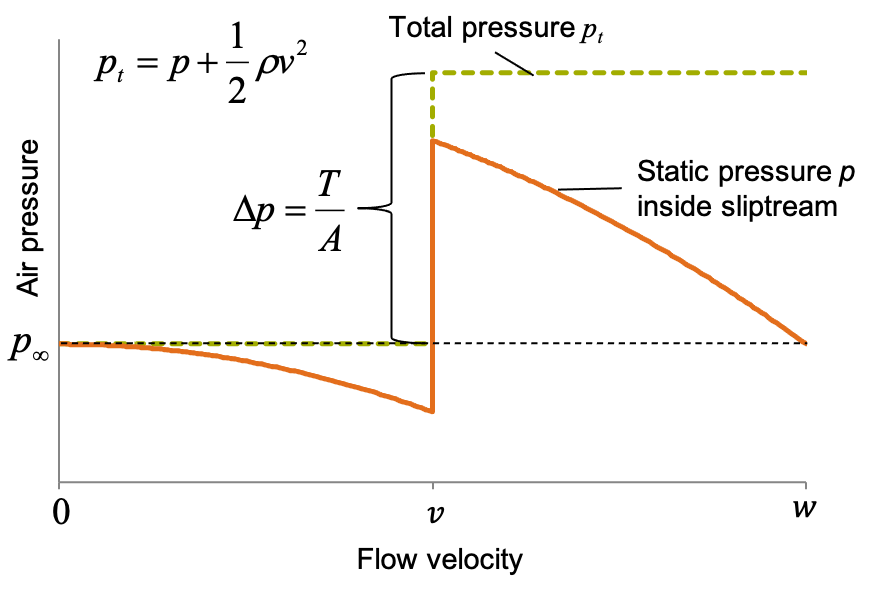
Hover slipstream pressure distribution
Note
Momentum theory, with its uniform inflow velocity assumption gives the lowest estimate of induced power. Its not due to the idealised flow conditions (i.e. neglecting certain phenomena that contribute to disspative power loss) but due to the uniform \(v\) assumption itself.
Aside: T/P, DL, MTOW
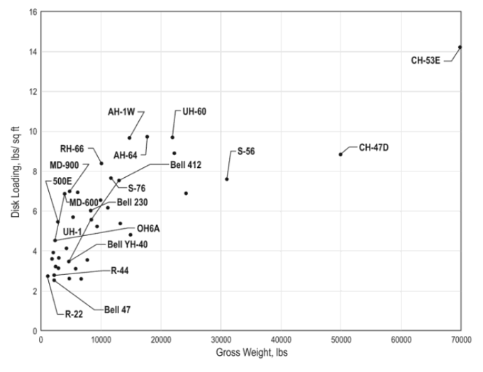
DL vs MTOW [taken from Helicopter Aerodynamic II by RW Prouty]
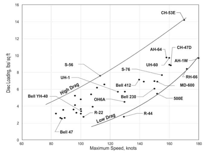
DL vs Speed [taken from Helicopter Aerodynamic II by RW Prouty]
T/P vs DL [taken from Helicopter Aerodynamic II by RW Prouty]
As is evident from the figures above, large helicopters tend to have smaller rotors (relative to their size) and thereby higher DL when compared to lighter helicopters. The rules of physics apply to all helicopters equally, so based on the above momentum theory derivation they must consume relatively higher power in hover than lighter helicopters (and they do!). This is because overall helicopter design, and the rotor design in particular, is not dictated by the sole criterion of having minimum power consumption during hover. A helicopter should exhibit efficient forward flight performance as well and having a smaller main rotor facilitates a relatively smaller fuselage 1 which leads to lower drag in forward flight. However, the DL vs speed chart indicates that the higher speed performance for helicopters has grown in tandem with the increase in MTOW. This is because of the presence of relatively larger engines on these designs that are necessary to deliver power during hover when the rotors have a high DL.
Summary
The rotor power obtained via this analysis is the best case scenario pediction. In reality it will always be higher.
no flow losses assumed
induced velocity is uniform over the disk
minimum induced power
it makes the rotor analysis problem computationally simple
in contrast, NSE implementation is anything but simple
provides basic intuitive understanding of thrust-power relation
Relevance of induced velocity?
The flow velocity at the rotor disk, \(v\), is called the induced velocity and is needed to accurately estimate blade aerodynamic loads. The flow velocity at far downstream, \(w\), is relevant for accounting for different rotor wake interaction phenomena - rotor-wing or rotor-fuselage interference effects, brownout, whiteout etc.
Detour: interference effects
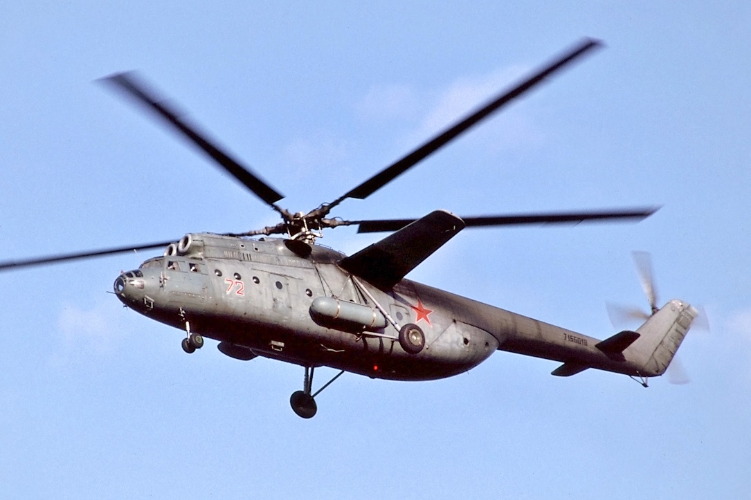
Mi-6 [source]
![[source]](https://en.wikipedia.org/wiki/Mil_Mi-6#/media/File:Mi-6_(cropped).jpg)
where \(k_{dl}\) is called the download factor. The induced velocity \(v\) is flow velocity at the rotor disk itself. Flow velocity impinging on the fuselage is not going to be very different from this value. If a lift-augmented design of the Mi-6 is considered, knowledge of \(v\) would directly give us a quantitative understanding of the download on the wing. Similarly, the download force experienced by the helicopter because of fuselage can be roughly ascertained.
Detour: brownout/whiteout
A fully loaded CH-53K (40,000 kg) would generate hurricane force winds
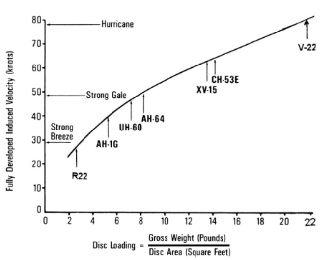
Induced flow velocity in the far wake (taken from Helicopter Aerodynamics Vol I by Ray Prouty)
from IPython.display import YouTubeVideo
YouTubeVideo('RODMMX3SOBs', width=700, height=500)
High induced velocities from the rotor can kick up dust/snow on unprepared landing grounds. This leads to degradation in visual cues that are necessary for pilots to maintain aircraft orientation.
Aside
Dust is even otherwise a major concern due to moving mechanical components involved. Heavy maintainance is warranted when operating in a dusty environment.
“… (during the Vietnam war) dust put more helicopters out of commission than enemy action”
“… America’s elite rescue force had lost eight men, seven helicopters, and a C-130, and had not even made contact with the enemy. It was a debacle. It defined the word “debacle.””
— article detailing the failed Iran hostage rescue attempt by American Delta forces (an unexpected dust cloud encountered en-route was one of the leading causes of the failure)
Its not all bad though. Some really pretty pictures can be obtained when sand particles strike rotor blades. — Kopp–Etchells effect
Mathematical formulation: Climb
Climbing rotor flowfield model in momentum theory
substitute \(2v\) and solve quadratic equation in \(v\)
So climbing reduces the induced velocity!
Two question
Does lower induced velocity \(v\) mean climbing rotor consumes lower power than hover!?
Why is the other root ignored?
For steady climb case
but in climb \(\dot{m} = \rho A(V+v) > \rho A v_h\) so momentum imparted to the air is the same but the velocity is smaller.
Total power required in climb = Climb power (\(TV\)) + induced power (\(Tv\))
Other root indicates that flow at the rotor disc is in opposite direction (bottom to top) which is not physically viable
Further applications
propeller driven aircraft
VAWT/HAWT wind turbines
tidal turbines
Turbines of different kinds [source]
![[source]](https://commons.wikimedia.org/wiki/File:HAWT_and_VAWTs_in_operation_medium.gif)
Limitations
Momentum theory only takes into account the rotor disc area. It does not take into account other rotor geometry parameters - blade twist, taper, chord, sweep angle (forward and back), anhedral/dihedral angle, or aerodynamic parameters - airfoil type.
rotor geometry not modelled
rotor torque not modelled
i.e. blade drag due to rotational velocity
no losses modelled
swirl flow, viscous drag
Does not include aerodynamic limitations of an airfoil
only maps thrust to induced velocity
Modelling losses in momentum theory
The fact that the rotor is not an actuator disk but rather a geomteric entity with finite number of lifting surfaces (blades) leads to physical phenomena that have not been mentioned in the above discussion or the derivation of the results. Consequently, the derived momentum theory results do not include their effects. Turns out these effects are non-negligible and can result in an error of atleast 10-15% in the power calculation of most rotors if not accounted for. So, the way they are accounted for is using an empirical (i.e. based on experimental results) parameter called induced power factor \(\kappa\). It is an adjustment adopted because momentum theory is not perfect.
tip losses
blade root cutout
non-uniform induced velocity
swirl in rotor wake
While \(\kappa\) helps improve the power prediction using momentum theory, all the shortcomings of momentum theory discussed earlier still persist. For e.g. nothing in the equation above tells us whether a rotor designed for (say) a 5-ton helicopter would also be able to generate 100-tons of thrust! Obviously, the answer is no. The fact that airfoil blades would stall after a certain point and fail to generate any further lift is simply not included in any form within the assumptions or the derivation (go ahead, scroll up and convince yourself that that is the case!) There are no free lunches. Since the momentum theory is based on approximations introduced to the NSE, we cannot obtain all information about the rotor operation or as quantitatively accurate results as can potentially be obtained using NSE. In other words the momentum theory approximations are appropriate in certain scenarios and as a consequence the theory will lead to pretty reliable results. In a lot of other scenarios where the approximations don’t apply or are violated, the results will be bad.
Right application context
Provides good estimate in steady conditions - climb, hover, (limited range) descent
models only the dominant physics exhibited by rotors in steady state operation
used extensively in preliminary design
relation between T, P, \(v\), DL is desired
easy to see direct cause and effect relations
“…momentum approach may provide a clarity of the overall picture that could be lacking when more complicated theories are applied” [Ste79]
Not so right application context
heavily loaded rotor
for e.g. tiltrotors
sudden changes in blade geometry - twist, taper, sweep etc.
Transient conditions - for e.g. maneuvers
A higher fidelity (i.e. better) model is required to overcome the limitations of momentum theory. This is where the blade element momentum theory (BEMT) comes in!
- 1
In the case of a conventional design, for e.g., the tail rotor cannot in the wake of the main rotor since ingesting the distrubed wake of the main rotor can lead to fluctuating performance of the tail rotor. So the tail boom length will grow in size together with the main rotor. In order to keep the helicopter CG close to the rotor chaft, the front of the fuselage will need to be expanded. This not only makes the overall design much heavier but also increases its parasite drag.