Figure of Merit
Contents
Figure of Merit
The figure of merit of a rotor is a quantity that is used to assess its efficiency in hover. It is defined as follows-
Here the ‘minimum power required to hover’ corresponds to the hover power required by an ideal rotor with uniform inflow - since that is the ideal scenario that results in minimum power consumption. Additionally, no viscous losses are assumed. So the quantity in the numerator is dictated by the momentum theory result. When using computational analysis to obtain the FM of a rotor, as against experimental measurement, the ‘actual power’ of the rotor includes the profile power component as a minimum. The idea is to use a higher fidelity theory than momentum theory since otherwise the result would be that the FM=1, which means the rotor under consideration is an ideal rotor by default. The FM of a real rotor is always less <1 and, in practice, usually lies between 0.5-0.7.
Using the blade element momentum theory results in the following expression.
Aside
Is it possible to experimentally obtain the induced power of a rotor?
From the expression above, it is evident that FM is a function of \(C_T\) as well as \(C_{d0}\). The dependence of \(C_{d0}\) is more apparent - higher \(C_{d0}\) leads to low FM. This is a natural result considering that low FM means that the rotor is not so efficient. The FM varies with the thrust generated by the rotor and is shown schematically below (\(\delta\) here refers to \(C_{d0}\) and the notation used for figure of merit is \(M\)).
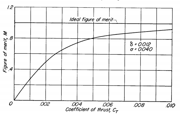
FM vs CT [taken from Aerodynamics of the Helicopter by A Gessow]
Based on the definition in Eq. \(\eqref{eq:FM_def}\), a high FM is desirable. Then, from the figure shown above, the rotor design has to be such that it operates at a high \(C_T\) value in hover. This is a straightforward result of the \(C_T\)-terms in Eq. \(\eqref{eq:FM1}\) outweighing the \(C_{d0}\)-term and eventually approaching a value of \(1/\kappa\). This raises questions though - is it even advisable to operate the rotor at high \(C_T\) in order to realise a high FM\(\rightarrow 1/\kappa = 1/1.15\approx 0.87\)? or does Eq. \(\eqref{eq:FM1}\) even hold in this high \(C_T\) range?
A high \(C_T\) implies that the blade sections are operating at a high mean lift coefficient. Which is not a problem in of itself but the rotor is expected to generate larger thrust in forward flight in order to counter both the drag as well as the weight of the aircraft. Designing the rotor such that it operates at a high \(C_T\) in hover would reduce the margin of thrust available in forward flight and limit the aircraft’s performance. Additionally, the drag coefficient of the blade sections would not stay at the minimum value of \(C_{d0}\) when they generate higher and higher lift. So the profile power coefficient term in Eq. \(\eqref{eq:FM1}\) would actually increase as well, and fairly dramatically at that if you recall the \(\alpha\) vs \(C_D\) plots of NACA23012 from earlier.
Comparing rotors using FM
Alternately, the FM can also be written as-
From the above expression, a casual observer might be misled into thinking that a higher \(DL\) is desirable since it leads to a higher FM. However, from the momentum theory model we now know better. Since Eqs. \(\eqref{eq:FM1}\) and \(\eqref{eq:FM2}\) are equivalent, high \(DL\) models the same effect as that of high thrust (and ergo high induced power) and a correspondingly lower weighting of the profile power. Therefore, whenever the two different rotors are compared against each other using FM the comparison is always carried out for the same \(DL\) for a more ‘apples-to-apples’ comparison.
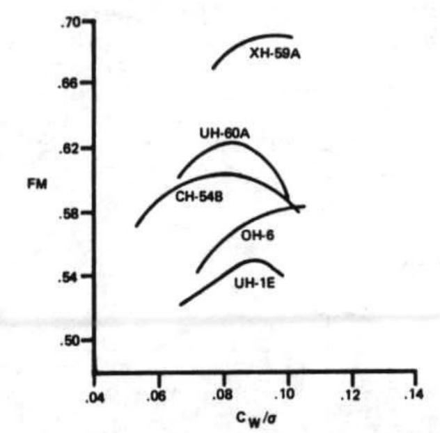
FM of some well known designs [source]